Controlador MIDI casero con Arduino
Hoy vamos a construir un controlador MIDI con el que podremos tocar la batería, el piano, o componer música electrónica. Para ello programaremos un Arduino para que reciba las señales que mandan unos pulsadores y la transforme en impulsos MIDI (información musical como una nota, el compás o el tono), esta información será enviada al ordenador y un software la transformará en sonido. Según el software será un instrumento u otro.
La idea del proyecto no es mía, por Internet ya rulan varios diseños (yo me he basado en éste y lo he simplificado), aunque sin duda el mio es el más Low cost y fácil de realizar. Os pongo un vídeo para que lo veáis en acción:
Necesitaremos un arduino (yo he usado el nano v3), 7 pulsadores, 7 resistencias de 10k, una interface midi, y un cable midi. La mayoría de los proyectos que existen por internet no envían señales midi, si no que usan el puerto serie y luego un programa en el ordenador se encarga de convertir esa señal en midi, y otro programa crea un puerto midi virtual que es el que envía la señal al software musical (batería, piano, etc…). A mi entender eso es más complicado y más engorroso, puesto que hace falta más configuraciones y programas.
Este montaje envía directamente señales midi a una interfaz, y el software musical lo interpreta del tirón. Ya explicado pasamos a la acción:
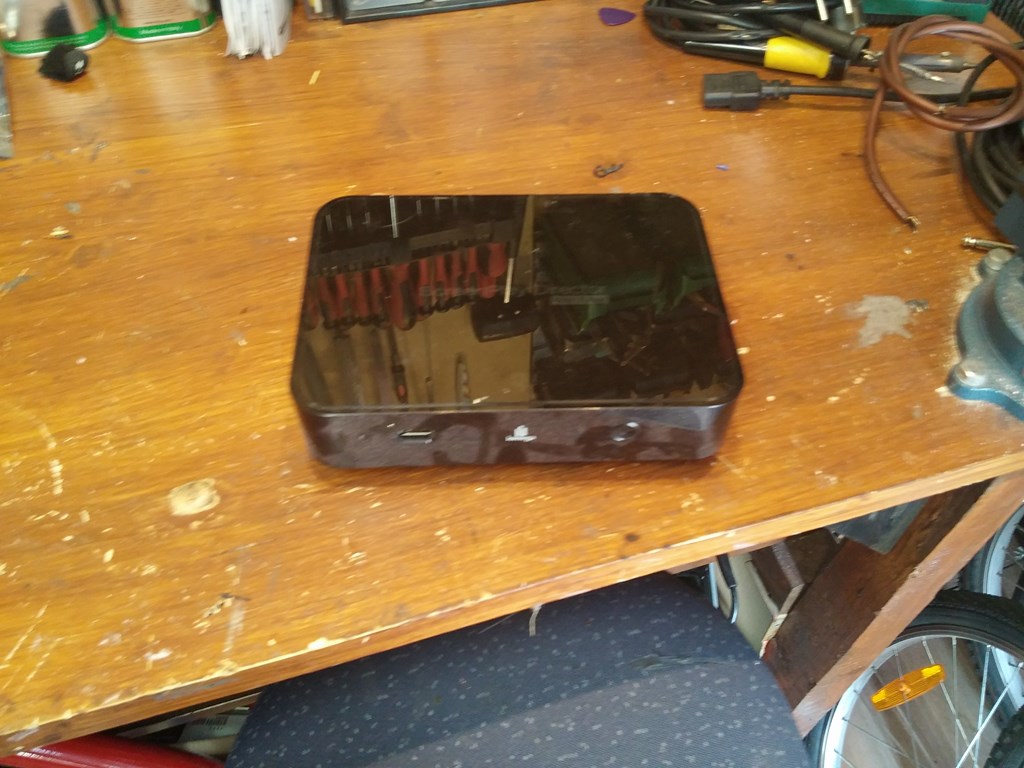
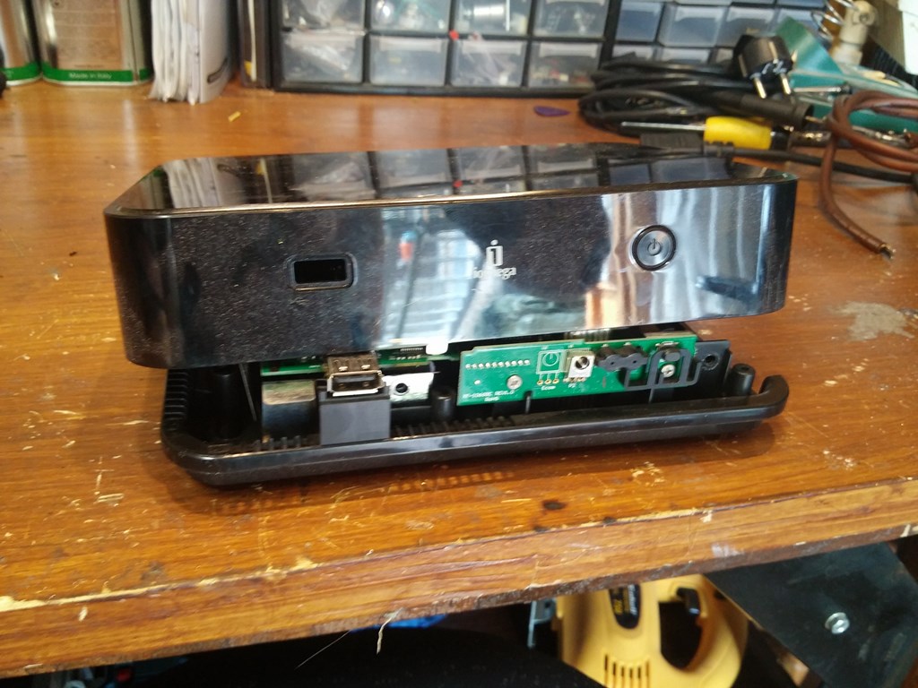
Tenia por casa esta caja proveniente de un disco duro multimedia que murió:
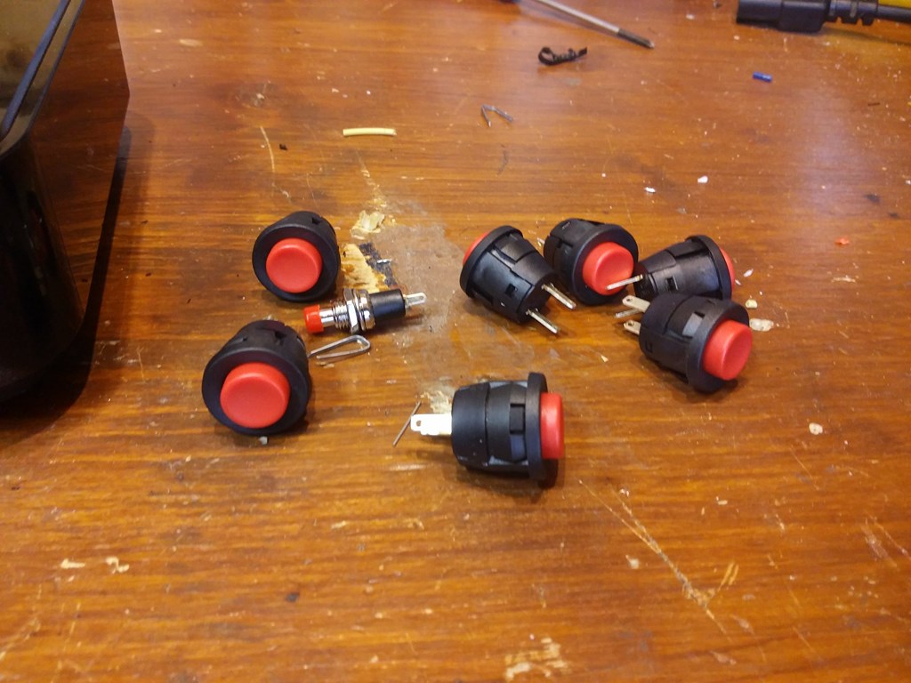
Por otro lado aquí tenemos los pulsadores, nada del otro mundo. Los podéis comprar en cualquier tienda de electrónica o por internet. A mi me costaron menos de 5€ todos.
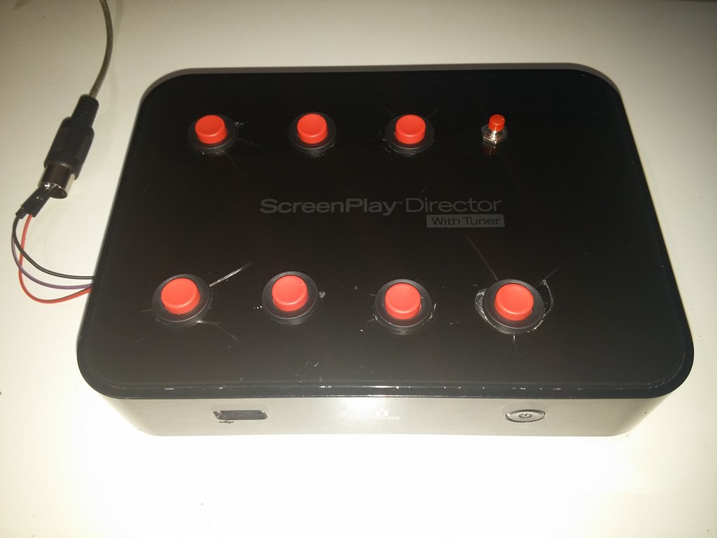
Agujeré vilmente la caja y fui colocando los pulsadores
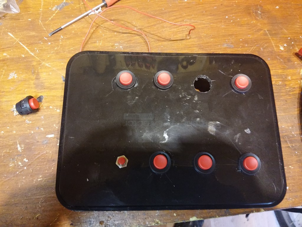
Cómo veis hay un pulsador diferente, sirve para cambiar de octava, es decir sube la nota una octava haciéndola más aguda.
Luego se cablean los pulsadores, en un pin les suministramos los 5 voltios que provienen del arduino, y en el otro una resistencia de 10K que sirve para evitar rebotes, si no la ponemos el arduino puede creer que hemos apretado el botón varias veces cuando en realidad sólo hemos apretado una vez.
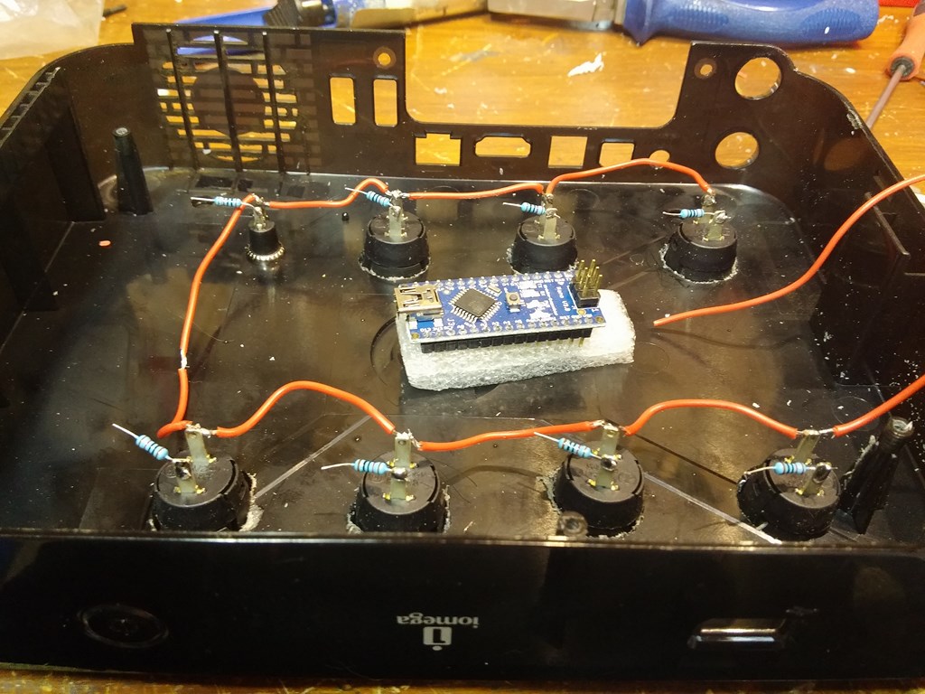
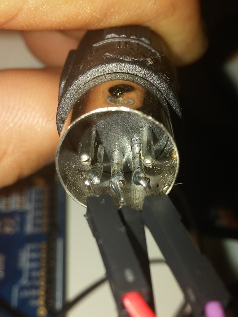
Cada resistencia la conectaremos a masa y a cada pin del Arduino. El conector midi lo soldaremos al cable que sale del pin TX del arduino, a masa y a los 5V con una resistencia de 220 ohms. En la imagen se ve que yo lo he soldado directamente a los pins de un cable macho-macho, pero lo suyo es hacerlo en un conector hembra.
Os pongo un esquema hecho en Fritzing para que lo veáis más fácil

Y ahora nos toca programar el arduino. Este código es una versión simplificada y reducida del controlador en el que me he basado. Abrimos el IDE de Arduino, copiamos el siguiente código y lo compilamos.
Código
//Allocate the buttons to the digi IOs on the board, pins 2-7
#define BUTTON1 2
#define BUTTON2 3
#define BUTTON3 4
#define BUTTON4 5
#define BUTTON5 6
#define BUTTON6 7
#define BUTTON7 8
//Connect the LEDs to the digi IOs on the board, pins 8-13
//Use the AO as a “shift” key to double
// the number of usable pitches/button
#define SHIFT_KEY A0
//For now, all midi commands are on channel 1
#define CMD_1 0x90
#define CMD_2 0x90
#define CMD_3 0x90
#define CMD_4 0x90
#define CMD_5 0x90
#define CMD_6 0x90
#define CMD_7 0x90
//With medium velocity
#define VEL_1 0x45
#define VEL_2 0x45
#define VEL_3 0x45
#define VEL_4 0x45
#define VEL_5 0x45
#define VEL_6 0x45
#define VEL_7 0x45
//Define the pitches, so we don’t have to keep looking
// up the hex / midi chart
#define PITCH_1 0x3F //D#
#define PITCH_2 0x40 //E
#define PITCH_3 0x41 //F
#define PITCH_4 0x3E //D
#define PITCH_5 0x3D //C#
#define PITCH_6 0x3C //Middle C (C4)
#define PITCH_7 0x45 //A
#define PITCH_8 0x46 //A#
#define PITCH_9 0x47 //B
#define PITCH_10 0x44 //G#
#define PITCH_11 0x43 //G
#define PITCH_12 0x42 //F#

boolean changeState1 = false;
boolean changeState2 = false;
boolean changeState3 = false;
boolean changeState4 = false;
boolean changeState5 = false;
boolean changeState6 = false;
boolean changeState7 = false;
boolean currentState1 = false;
boolean currentState2 = false;
boolean currentState3 = false;
boolean currentState4 = false;
boolean currentState5 = false;
boolean currentState6 = false;
boolean currentState7 = false;
void setup()
{
//Set up the digi IOs as inputs for the buttons
pinMode(BUTTON1, INPUT);
pinMode(BUTTON2, INPUT);
pinMode(BUTTON3, INPUT);
pinMode(BUTTON4, INPUT);
pinMode(BUTTON5, INPUT);
pinMode(BUTTON6, INPUT);
pinMode(BUTTON7, INPUT);
//Set up the digi IOs as outputs for the LEDs
//Set the analog 0 pin as a digi input (no digi IOs left)
pinMode(SHIFT_KEY, INPUT);
// Set MIDI baud rate:
Serial.begin(31250);
}
void loop()
{
//Read all of the buttons, then store into state bool vars
if(digitalRead(BUTTON1) == HIGH) {currentState1 = true;}
else {currentState1 = false;}
if(digitalRead(BUTTON2) == HIGH) {currentState2 = true;}
else {currentState2 = false;}
if(digitalRead(BUTTON3) == HIGH) {currentState3 = true;}
else {currentState3 = false;}
if(digitalRead(BUTTON4) == HIGH) {currentState4 = true;}
else {currentState4 = false;}
if(digitalRead(BUTTON5) == HIGH) {currentState5 = true;}
else {currentState5 = false;}
if(digitalRead(BUTTON6) == HIGH) {currentState6 = true;}
else {currentState6 = false;}
if(digitalRead(BUTTON7) == HIGH) {currentState7 = true;}
else {currentState7 = false;}
//Flush the serial buffer
Serial.flush();
//If the button is pressed
if(currentState1 == true) {
//set the led pin state to on
//If this is the first reading after pressing
if(currentState1 != changeState1){
//send command to start corresponding note
writeNote(CMD_1, PITCH_1, VEL_1);
}
}
//If the button is not pressed
else{
//set the led pin state to off
//if this is the first reading after releasing
if(currentState1 != changeState1){
//send the command to stop corresponding note
stopNote(CMD_1, PITCH_1);
}
}
//Repeats for each button/LED/pitch
if(currentState2 == true) {
if(currentState2 != changeState2) {
writeNote(CMD_2, PITCH_2, VEL_2);
}
}
else{
if(currentState2 != changeState2){
stopNote(CMD_2, PITCH_2);
}
}
if(currentState3 == true) {
if(currentState3 != changeState3) {
writeNote(CMD_3, PITCH_3, VEL_3);
}
}
else{
digitalWrite(10, LOW);
if(currentState3 != changeState3){
stopNote(CMD_3, PITCH_3);
}
}

if(currentState4 == true) {
if(currentState4 != changeState4) {
writeNote(CMD_4, PITCH_4, VEL_4);
}
}
else{
if(currentState4 != changeState4){
stopNote(CMD_4, PITCH_4);
}
}
if(currentState5 == true) {
if(currentState5 != changeState5) {
writeNote(CMD_5, PITCH_5, VEL_5);
}
}
else{
if(currentState5 != changeState5){
stopNote(CMD_5, PITCH_5);
}
}
if(currentState6 == true) {
if(currentState6 != changeState6) {
writeNote(CMD_6, PITCH_6, VEL_6);
}
}
else{
if(currentState6 != changeState6){
stopNote(CMD_6, PITCH_6);
}
}
//Keep a record of the previous state, so we can monitor
//button state changes
changeState1 = currentState1;
changeState2 = currentState2;
changeState3 = currentState3;
changeState4 = currentState4;
changeState5 = currentState5;
changeState6 = currentState6;
changeState7 = currentState7;
}
void writeNote(byte command, byte pitch, byte velocity)
{
//Check if our “Shift” key has been pressed
if(digitalRead(SHIFT_KEY) == HIGH)
{
//Play the pitch in the higher section of the octive
Serial.write(command);
Serial.write(pitch+6);
Serial.write(velocity);
}
else
{
//otherwise play the pitch from the lower section
// of the octave
Serial.write(command);
Serial.write(pitch);
Serial.write(velocity);
}
}
void stopNote(byte command, byte pitch)
{
//No way to know (without keeping track of which pitch was
// played for each button) which pitch to turn off,
//So switch them both off
Serial.write(command);
Serial.write(pitch);
Serial.write(0x00);
Serial.write(command);
Serial.write(pitch+6);
Serial.write(0x00);
}
Una vez tengamos todas las conexiones hechas y el arduino esté programado, tendremos que conectar nuestro controlador midi a la tarjeta de sonido o interfaz midi, que es la que los recibirá. Yo ya tenía una interfaz, pero si no tenemos, no problem. Aquí podemos comprar un adaptador de midi a usb por 6’18€. Después de conectarla abrimos nuestro software musical (DAW) y podemos dar rienda suelta a nuestra creatividad.
El potencial de este invento es muy grande y variado, pese a ser un controlador midi de pocas notas (6 notas que se convierten en 12 al cambiar de octava) ya nos será posible hacer nuestros ritmos y dar rienda a nuestra creatividad, y todo con muy poca inversión:
| Arduino nano | 6'87 |
| 7 Pulsadores | 4'9 |
| 7 Resistencias 10K y 1 de 220ohm | 0'6 |
| TOTAL | 12'37 |
|---|
buenísimo proyecto , pero no me queda claro donde va la alimentación sld
Hi, Wil.
Lo tomo en cuenta; acabo de empezar en Arduino, porque me ha dao el puntazo el cajon-e, que todavía no lo han comercializado (Buscalo en Youtube, cuando conecta al ampli).
Lo que yo pretendo es no usar el ordenata para esto, sino la Arduino Musica Shield de Sparkfun; sería interconectar tx/rx correspondiente y salida audio de la MIS con un ampli.
La hostia sería una LCD táctil, para poder seleccionar el instrumento midi…
Una duda: Cuando hablas de octavas, son notas, no?
Abrazos
no se puede hacer para q se conecte via usb a la pc?